1. Project Objective
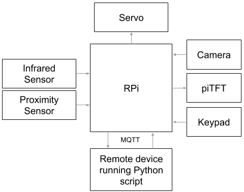
Our final project aims to integrate the RPi, piTFT, various sensors, a servo, and a remote device into one smart door lock system that can function on its own and provide various methods of allowing/denying entry for user convenience in multiple scenarios by implmenting software and building hardware modules that are reliable.
2. Introduction
Smart lock is an embedded system built upon a RPi that allows for automatic entry for residents within a home and denial for non residents. The system comprises of a deadbolt-turning mechanism attached to the door lock of the front entry of a home and various sensors that trigger the turning of the lock with minimum human intervention. The mechanism consists of a high torque servo attached to the door and deadbolt via 3D-printed mounts. The system has two states, locked and unlocked, with a default locked state and multiple ways to toggle between them.
The first way to unlock the door is from the inside, via an infrared sensor attached near the door knob, which triggers the mechanism to turn the deadbolt when it senses objects (hands) in its vicinity. The second way to unlock the door is via facial recognition from the outside of the door. A camera and a proximity sensor are attached to the peephole location and the camera captures the faces of passing people whenever the proximity sensor signals that an object (a person) is close. When the camera captures the faces of the home residents, the facial recognition software recognizes their faces with a certain confidence level and triggers the mechanism to turn the deadbolt from the inside. The third way to unlock the door is to enter a passcode via a keyboard attached to outside the door underneath the peephole. Non-resident visitors who frequent the residence may be told of a special passcode that, when the correct sequence of inputs is captured by the Pi, triggers the mechanism to unlock the door. Yet another method to unlock the door is to request access via the keypad. Visitors (non residents) of the door can press the star button on the keyboard, which triggers the camera to capture an image of the visitor and the image is sent to the device of the residents. Upon discerning who is outside, the residents can grant access to the visitor from their remote devices via prompts by the Python script and entering the password aforementioned. The last method to unlock the door functions similar to a glorified peephole. When the outside camera is turned on, the RPi displays real life footage of the outside on the piTFT, which is attached to the inside of the door. The residents can choose to allow entry or ignore the visitors completely via button prompts on the piTFT.
Moreover, whenever the system is unlocked, it will return to its locked state after a fixed period of time to prevent unwanted visitors from entering the residence so the residents do not have to manually juggle keys to do so, and in case they forget to do so.
3. Hardware Design
a. Mechanical
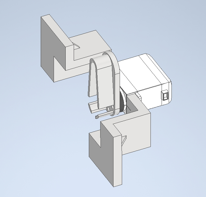
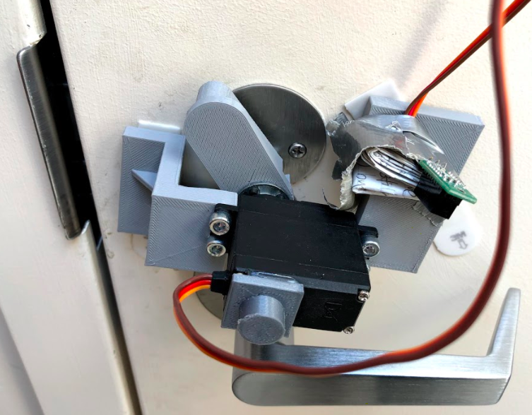
The lock turning mechanism is composed of three parts: the lock turner, servo and lock turner interface, and two servo mounts. The lock turner interface is attached to the exposed gear of the servo and the lock turner is bolted onto the lock turner interface via M3 screws. Both the lock turner’s and the interface’s attachment to the servo are reinforced through the servo center screw. The servo is then bolted to the two servo mounts via the four mounting holes available on its body. The servo mount attaches to the door via command strips, holding the mechanism in place. The entire assembly is shown in figure 2 below.
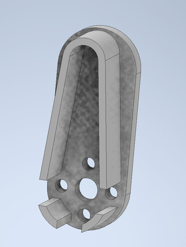
The lock turner is shown in figure 3 below. The geometry was obtained by taking caliper measurements of the deadbolt. Those measurements were enlarged by 1mm - 2mm to allow room for measurement errors and 3D printing tolerances to ensure a loose fit onto the deadbolt but aiming for a slightly nicer slip fit. When assembled, the lock turner acts as the anti-geometry of the deadbolt. The center hole on the lock turner is a clearance hole for the max diameter of the servo gear, the four smaller holes surrounding it are attachment holes to bolt the lock turner to the interface. This part was manufactured via 3D printing.
The lock turner to servo interface as pictured in figure 4 below is a store bought component that is either machined out of metal or made from injection molded nylon. It’s main purpose is to connect the servo and the lock turner in a reliable manner. As will be detailed in the servo section below, the output torque of the servo, transmitted through the gear, is rather high, the teeth of the gear will strip the lock turner if the lock turner is directly attached to the servo, since 3D printed plastics do not exhibit high strength. As a side note, 3D printing does not allow the user to print gear splines so attaching the lock turner to the servo directly would be rather difficult. However, since the interface is either made from higher strength materials or manufactured in a more reliable way, stripping the interface at the attachment point is more difficult, and thus using the attachment would make the hardware more reliable.
The servo mounts are shown in figure 5 below. The holes are for mounting the servo and are the pre drill hole diameters of the mounting screw since 3D printers cannot print threads. Because the servo mounts are also made from 3D printed plastic, the material is relatively deformable. During assembly, the threads on the bolts will guide itself into the hole to form the counter threads automatically as it bolts down.
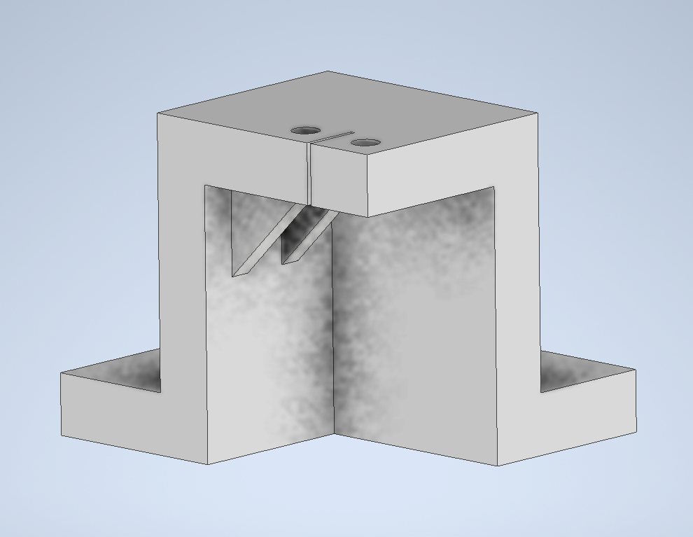
The lock turning assembly is supposed to ensure no interference between any of the components within the assembly during the entirety of the deadbolt’s motion range and clear other structures on the door like the doorknob, as shown in the rough sketch to demonstrate the deadbolt’s motion path below.

However, when actually assembled together, the servo mounts did interfere with the base of the doorknob and while this did not prevent the assembly from functioning and cause any internal interferences, the assembly had to be placed at an angle on the door.
b. Electrical
Sensors
For detecting users on the inside trying to leave the house, we use a Sharp GP2Y0D810Z0F digital distance sensor. According to the datasheet, the infrared sensor uses a simple one-line communication protocol and "the output voltage of this sensor stays high in case an object exists in the specified distance range", which is 10cm in our case.
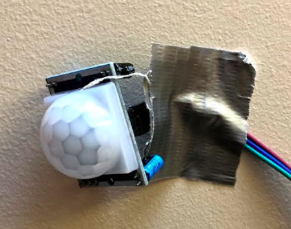
To detect approaching users from the outside, we use a HC-SR501 PIR sensor with the following datasheet. It uses a similar one-line communication protocol with two potentiometers for the sensing distance and the induction delay. This is not our preferred sensor as the sensor output does not go low immediately following the absence of human activity. The RCWL-1601 distance sensor is much more preferable as it provides precise distance measurements in real time. Unfortunately, its library conflicts with the RPi camera for unknown reasons. Since the camera is vital to our project, we decided to switch.
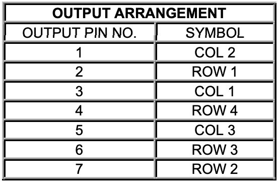
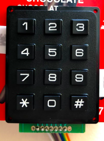
Keypad
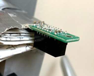
For password detection and sending remote requests, we use a 3x4 matrix keypad. Adafruit, however, does not provide a datasheet for this product and the datasheet was not discovered until the time of writing. As seen below, the diagram on the left follows a standard approach to matrix keypads. However, the pin configuration on the right is extremely counter-intuitive and added unnecessary difficulty to this part of the project.

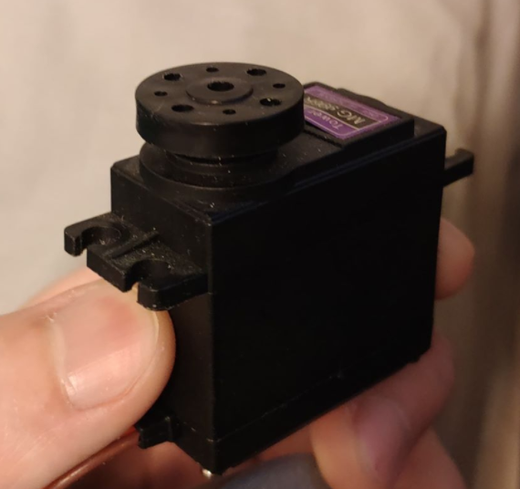
Servo
Since the deadbolt needed to turn is on the slightly tighter and heavier side, and the design of the lock turning mechanism does not provide additional mechanical advantage, the servo chosen is the Tower Pro High-Torque MG996R. According to the datasheet, this servo can output a stall torque of 9.4 kgf·cm at 4.8V and 11 kgf·cm at 6V. We decided to power the servo using the 5V output from the RPi, which is within its operating voltage of 4.8V - 7.2V. Therefore, the stall torque we expect is 9.67 kgf·cm, or 0.95 Nm, assuming the torque produced varies linearly with the input voltage. This torque spec is about 5 times that of the continuous Parallax servo used in lab and, upon testing, is indeed strong enough to turn the deadbolt. We chose to power the servo off the RPi to decrease complexity in our system hardware (no need to attach a battery holder) and to prevent battery drains, since the RPi is directly plugged in.
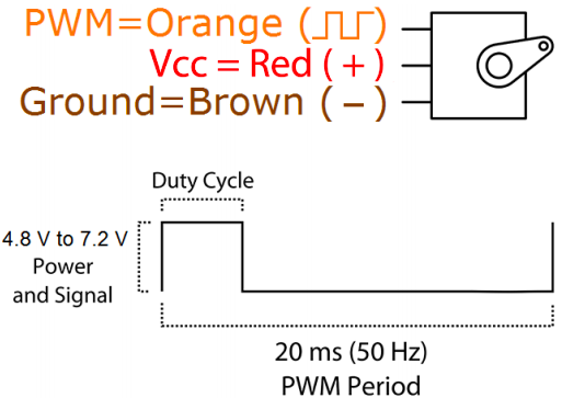
Three wire are connected to the servo: signal (orange), red (power), and ground (brown). Signal is connected to a GPIO pin on the RPi, power is connected to 5V power output from the RPi, and ground shares a connection with RPi's ground.
As for the communication protocol, the servo uses PWM with a period of 20ms, or 50Hz, and a duty cycle of 1ms - 2ms. Unlike the continuous servo used in lab where the duty cycle controls the speed at which the servo rotates, the MG996R is a positional servo where the duty cycle controls the position the servo is trying to spin to. We determined the lock and unlock position duty cycles to be at 1.9 and 1.3 respectively by test fitting the lock turner assmebly onto the deadbolt. At the aforementioned positions, the deadbolt is at just the right position so that the door is locked/unlocked without the servo straining to turn the deadbolt beyond its motion range.
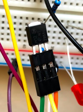
To conserve power, and to prevent any unwanted servo behaviors, a p-channel MOSFET is connected between the servo power pin and the RPi 5V pin. Within the lock and unlock functions inside the Servo class, which will be discussed later, the function first turns on the MOSFET, then waits 0.8 seconds after setting the PWM duty cycle to allow the lock to turn to the correct position before turning off the power.
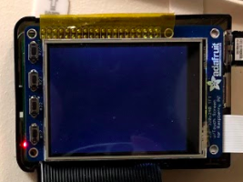
PiTFT
Ever since lab 1, our RPi has had a 2.8" TFT + resistive touchscreen attached. With the following schematic.

This component has been proven useful at times and troublesome at others. Since it is already there, we figured that we might as well make use of it. We would use it in combination with the camera by displaying real-time footage of the outside and actions that can be controlled through the touchscreen if the PIR sensor is activated. However, it uses many pins and we had to study the datasheet again to find pins that are available. Since our keypad uses 7 pins in total, we are actually somewhat close to using up all the pins.
Pin Configuration
After careful arrangements, we came up with the following pin configuration to avoid conflicts with the piTFT.
| Function | Pin | Pin | Function |
| 3V3 | 5V | ||
| BCM 2 | 5V | ||
| BCM 3 | GND | ||
| Keypad 5 | BCM 4 | BCM 14 | |
| GND | BCM 15 | ||
| Keypad 6 | BCM 17 | BCM 18 | |
| Keypad 7 | BCM 27 | GND | |
| Servo Control | BCM 22 | BCM 23 | |
| 3V3 | BCM 24 | ||
| BCM 10 | GND | ||
| BCM 9 | BCM 25 | ||
| BCM 11 | BCM 8 | ||
| GND | BCM 7 | ||
| BCM 0 | BCM 1 | ||
| MOSFET Gate | BCM 5 | GND | |
| BCM 6 | BCM 12 | Keypad 4 | |
| Inside | BCM 13 | GND | |
| BCM 19 | BCM 16 | Keypad 3 | |
| Outside | BCM 26 | BCM 20 | Keypad 2 |
| GND | BCM 21 | Keypad 1 |
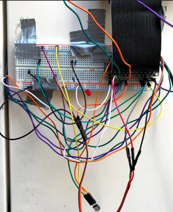
And the final breadboard layout looks like this.

4. Software Design and Testing
All of our source code can be found here.
a. Modules
In order to maintain hierarchy, modularity, and encapsulation, we implemented different classes for each component with key functions. For example, for the servo, we simply pass in two pins to construct an object, and call the lock and unlock functions. This allows us to easily alter low-level implementations without altering the high-level behavior. When we discovered that the HC-SR04 library used by the ultrasonic distance sensor has a conflict with the RPi camera, we quickly changed the internal implmentation without changing the main program and everything performed as expected afterwards. Having different modules also enables easier testing as unit testing becomes possible.
For the inside and outside sensors, we simply need a present() function that returns whether there are currently people on the inside/outside. They are also simple GPIO inputs, and therefore has very straightforward implementations.
class InsideSensor:
    def __init__(self, pin):
        GPIO.setmode(GPIO.BCM)
        GPIO.setup(pin, GPIO.IN)
        self.pin = pin
    def present(self):
        return not GPIO.input(self.pin)
For the servo, we added a few more lines to control the MOSFET, but the implementation is still very straightforward, providing functions to lock and unlock the door.
class Servo:
    def __init__(self,signal_pin,power_pin):
        # signal pin gives PWM output to control servo
        # power pin turns on/off the MOSFET that provides power
        GPIO.setmode(GPIO.BCM)
        GPIO.setup(signal_pin, GPIO.OUT)
        GPIO.setup(power_pin, GPIO.OUT)
        self.power = power_pin
        self.servo = GPIO.PWM(signal_pin, 50)
        self.servo.start(0)

    def changePosition(self,DC):
        self.servo.ChangeDutyCycle(DC*5)

    def lock(self):
        # turn on MOSFET
        GPIO.output(self.power,0)

        lock_pwm = 1.3
        self.servo.ChangeDutyCycle(lock_pwm*5)
        # give time to turn
        time.sleep(0.8)
        # turn off MOSFET
        GPIO.output(self.power,1)

    def unlock(self):
        GPIO.output(self.power,0)
        unlock_pwm = 1.9
        self.servo.ChangeDutyCycle(unlock_pwm*5)
        time.sleep(0.8)
        GPIO.output(self.power,1)
For the keypad, we use the library provided by Adafruit. However, as mentioned in 3b, the pin order is completely scrambled and we had to determine what each pin is experimentally. In the end, we were able to determine the order and return the key(s) currenlty being pressed.
class Keypad:
  def __init__(self, pins):
    # order scrambled, see datasheet
    cols = [digitalio.DigitalInOut(x) for x in (pins[3], pins[1], pins[5])]
    rows = [digitalio.DigitalInOut(x) for x in (pins[2], pins[7], pins[6], pins[4])]
    keys = ((1, 2, 3), (4, 5, 6), (7, 8, 9), ("*", 0, "#"))
    self.keypad = adafruit_matrixkeypad.Matrix_Keypad(rows, cols, keys)
  def keys_pressed(self):
    return self.keypad.pressed_keys
All modules were tested by simple demo programs before we moved onto the next step.
b. Threads
Since there are multiple tasks the RPi has to perform, we turn to multi-threading using the threading library. For each thread, we create a class with a run() method in threads.py. For example, the inside and outside sensor threads run forever and periodically update the global variables in the config module.
# check inside sensor every 0.25s and write to the global variable
class InsideThread:
    def __init__(self):
        self.inside = InsideSensor(13)
    def run(self):
        while True:
            time.sleep(0.25)
            if (self.inside.present()):
                config.inside_present = 1
                # if there are people outside and user puts hand on the handle, unlock
                config.keypad_entry = config.password
            else:
                config.inside_present = 0
The keypad thread, however, only runs under certain circumstanes. Specifically, when there are people present on the outside. It then monitors the keypad entries, treating one continuous press, no matter how long, as one press, and updates a history of six entries. The history can then be compared in the main thread and determine whether to unlock the door.
class KeypadDetThread:
    def __init__(self):
        self._running = True
        keypad_pins = [0, board.D21, board.D20, board.D16, board.D12, board.D4, board.D17, board.D27]
        self.keypad = Keypad(keypad_pins)
    def terminate(self):
        self._running = False
        config.keypad_entry = [None, None, None, None, None, None]
    def run(self):
        INIT = 0
        PRESSED = 1
        state = INIT

        while self._running:
            # check the keypad every 0.1s
            time.sleep(0.1)
            pressed_keys = self.keypad.keys_pressed()
            # debounce with FSM so long presses are not registered as multiple presses
            if state == INIT:
                if len(pressed_keys) == 1:
                    # update history if one key is pressed
                    for i in range(5):
                        config.keypad_entry[i] = config.keypad_entry[i+1]
                    config.keypad_entry[5] = pressed_keys[0]
                    state = PRESSED
            elif state == PRESSED:
                if pressed_keys == []:
                    state = INIT
            else:
                state = INIT
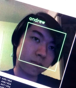
The most important thread is probably the facial recognition thread. Just like keypad detection, it only runs when there are users outside. Whenever the proximity sensor on the outside detects movement, the thread opens a RPi camera stream and starts recognizing faces. It does so through the following steps. First, during initialization, the script loads a pre-trained pickle model and a
Haar Cascade facial classifier into the class. Then, it grabs a frame from the video stream and performs simple image processing such as rotating and resizing so that the following steps could be run faster. After that, it uses the Haar Cascade classifier to determine to location of the face(s), and convert the face(s) into a 128-dimension vector(s). The vector(s) is compared with all the vectors in the pickle model and the Euclidean distance of each pair is calculated. If the minimum distance is below the tolerance specified, it is considered a match and the name corresponding to the entry in the pickle data is given. Finally, that name is written to a global variable so that the main thread can decide if unlocking is necessary. Everything described above is possible thanks to Adam Geitgey's face_recognition library and we adapted our code from Adrian Rosebrock's tutorial on Raspberry Pi face recognition. Training also follows a similar structure. encode_faces.py reads images from the dataset, determines the location of the faces, encodes them into 128-d vectors, and saves them to the pickle file. The dataset that we used contains two folders, one named Andrew with photos of Andrew, and one named Unknown with photos from a small open databse from AT&T.
# Credit: Adapted from https://www.pyimagesearch.com/2018/06/25/raspberry-pi-face-recognition/
class FacialRecThread:
    def __init__(self):
        self._running = True
        # takes a long time, loading once at boot
        self.data = pickle.loads(open("pi-face-recognition/encodings-cnn-large.pickle", "rb").read())
        self.detector = cv2.CascadeClassifier("pi-face-recognition/haarcascade_frontalface_default.xml")
    def terminate(self):
        self._running = False
    def run(self):
        # starts pi camera
        self.vs = VideoStream().start()
        while self._running:
            time.sleep(0.1)
            # grab the frame from the threaded video stream and resize it
            # to 500px (to speedup processing)
            frame = self.vs.read()
            frame = imutils.resize(frame, width=500)
            # camera at an angle
            frame = imutils.rotate(frame, angle=270)
            # save file for other threads
            cv2.imwrite("frame.jpg",imutils.resize(frame, height=240))
            # convert the input frame from (1) BGR to grayscale (for face
            # detection) and (2) from BGR to RGB (for face recognition)
            gray = cv2.cvtColor(frame, cv2.COLOR_BGR2GRAY)
            rgb = cv2.cvtColor(frame, cv2.COLOR_BGR2RGB)

            # detect faces in the grayscale frame
            rects = self.detector.detectMultiScale(gray, scaleFactor=1.1,
                  minNeighbors=5, minSize=(30, 30),
                  flags=cv2.CASCADE_SCALE_IMAGE)

            # OpenCV returns bounding box coordinates in (x, y, w, h) order
            # but we need them in (top, right, bottom, left) order, so we
            # need to do a bit of reordering
            boxes = [(y, x + w, y + h, x) for (x, y, w, h) in rects]

            # compute the facial embeddings for each face bounding box
            encodings = face_recognition.face_encodings(rgb, boxes)
            names = []

            # loop over the facial embeddings
            for encoding in encodings:
                # attempt to match each face in the input image to our known
                # encodings
                matches = face_recognition.compare_faces(self.data["encodings"],
                        encoding, tolerance=0.3)
                name = "Unknown"

                # check to see if we have found a match
                if True in matches:
                    # find the indexes of all matched faces then initialize a
                    # dictionary to count the total number of times each face
                    # was matched
                    matchedIdxs = [i for (i, b) in enumerate(matches) if b]
                    counts = {}

                    # loop over the matched indexes and maintain a count for
                    # each recognized face face
                    for i in matchedIdxs:
                        name = self.data["names"][i]
                        counts[name] = counts.get(name, 0) + 1

                    # determine the recognized face with the largest number
                    # of votes (note: in the event of an unlikely tie Python
                    # will select first entry in the dictionary)
                    name = max(counts, key=counts.get)

                # update the list of names
                names.append(name)
            config.names = names
        # release all resources so the pi camera doesn't run until the next time it is triggered
        self.vs.stop()
        time.sleep(0.1)
        self.vs.stream.release()
At first, we did not specify the tolerance level and we were getting a lot of misclassifications as random faces we found through google would be recognized as Andrew. After tweaking the parameters for a while, we found a spot that is both secure and functional. We tested dozens of faces and they are all recognized as unknown, and Andrew is recognized as Andrew properly.
The last thread in threads.py is the MQTT thread. MQTT is a light-weight messaging protocol used by many IoT devices, which fits our needs perfectly. It works by having three key parties, broker, publisher, and subscriber. The broker handles all message transactions between the publishers and subscribers. Publishers publish messages to the broker under specifi topics. Subscribers, if subscribed to those topics, will get those messages once sent. It is very simple and quite fast.
In our thread, we connect to a public broker at mqtt.eclipse.org if the keypad entry history contains a '*'. There are two topics/channels that our program uses to communicate. To transmit photos from the RPi to the user device, it uses the topic ece5725/smart-lock/req. To receive encrypted permission packages from the user device to the RPi, it uses the topic ece5725/smart-lock/resp. The way that the remote device tells the RPi whether to unlock the door is to send a hashed message with a timestamp. The program concatenates how many minutes it has been since the epoch and the password provided by the user, and run that string through a hashing algorithm. By hashing, the password is prevented from being transmitted through a public broker in plaintext. By adding the timestamp, man-in-the-middle attacks are prevented as the messages are only valid for a few minutes. Currently, we use MD5, which has been proven vulnerable under circumstances, as the hashing algorithm. This can be changed easily since our code is hierarchical. If the message the program receives matches one of the possible messages generated, the door successfully unlocks by remote control.
class MQTTThread:
    # verify message using the same encryption method
    # technically hashing so one-way, cannot decrypt
    def verify_password(self,_,__,msg):
        curr_time = int(time.time()/60)
        # give a 5-min window to account for inaccurate clock (maybe)
        for i in range(5):
            if(hashlib.md5((str(curr_time+i-2)+config.password_str).encode()).hexdigest().encode() == msg.payload):
                # if there is a match, unlock
                config.keypad_entry = config.password
        # if no match, reset entry history so that the request is sent only once
        if (config.keypad_entry != config.password):
            config.keypad_entry = [None, None, None, None, None, None]
        self.client.disconnect()
    def run(self):
        while True:
            try:
                # request at the door
                if ("*" in config.keypad_entry):
                    self.client = mqtt.Client()
                    # public MQTT broker provided by eclipse.org
                    self.client.connect("mqtt.eclipse.org",1883, 60)
                    # most recent image saved by facial rec thread
                    f = open("frame.jpg","rb")
                    self.client.publish("ece5725/smart-lock/req", bytes(f.read()))
                    f.close()
                    # wait for response
                    self.client.subscribe("ece5725/smart-lock/resp")
                    # callback function
                    self.client.on_message = self.verify_password
                    self.client.loop_forever()
            except:
                pass
Again, each thread is tested individually first before we moved onto the main program, which is how we found out that the HC-SR04 library conflicts with the camera. All threads work perfectly fine individually. When they were put together, the camera module started throwing errors out of nowhere. We then commented out the threads one by one until we found the source of the problem. We originally had a complicated workaround that was mostly functional but we ended up deciding that switching the sensor is much easier.
c. Remote Client
Our remote client script is very simple as well. It is the complement of the MQTT thread. To receive photos from the RPi, it uses the topic ece5725/smart-lock/req. To transmit encrypted permission packages to the RPi, it uses the topic ece5725/smart-lock/resp. Whenever it receives a message, it saves the payload as an image and opens a preview window. It then prompts the user for permission. If the user enters 'n', it sends that back as the response. If the user enters 'y', it prompts for a password. With that password, it creates an encrypted time-sensitive message using the same protocol as above and sends it back to the RPi. If the password is correct, the door will be unlocked remotely.
from PIL import Image
import paho.mqtt.client as mqtt
import hashlib
import time

client = mqtt.Client()
# public MQTT broker provided by eclipse
client.connect("mqtt.eclipse.org",1883,60)
client.subscribe("ece5725/smart-lock/req")

def on_message(client, userdata, msg):
    # write to local file
    f = open('frame.jpg', 'wb')
    f.write(msg.payload)
    f.close()
    # show the image
    image = Image.open('frame.jpg')
    image.show()
    if (input("Grant access? y/n\n") == "n"):
        client.publish("ece5725/smart-lock/resp","n")
    else:
        password = input("Please enter password\n")
        # encrypted time-sensitive message to provent MITM attacks
        message = hashlib.md5((str(int(time.time()/60))+str(password)).encode()).hexdigest()
        client.publish("ece5725/smart-lock/resp",message)
# recall method
client.on_message = on_message
client.loop_forever()
The first time we tested the thread working with the remote program, the client program opened about 50 windows in a couple of seconds before we were able to stop it. We realized that we had forgotten to clear to keypad history and therefore the thread keeps sending request over MQTT. We fixed that along with other encoding and hashing issues and the program worked as intended in the end.
d. Main
Our main.py handles all threads and unlocking/locking logic. It uses a FSM to keep track of states and many global varible provided by config.py to transition between states. During initilization, it sets up a Servo instance and all the threads, only running a few of them. It then enters an infinite loop since the program is designed to run continuously. The FSM starts in an INIT state, where nothing is done and the program simply goes back to sleep every 0.1s while the other threads work. When the inside thread changes the global variable, the FSM enters the INSIDE state and unlocks the door immediately, as the user inside intends to leave. After UNLOCK_DURATION (currently set at 15) seconds, it locks the door for user convenience as well as security reasons. It then goes back to the INIT state.
If the outside thread changes the global variable, the FSM enters the OUTSIDE state and starts the keypad detection thread and the facial recognition thread. It then checks the global variable changed by these two threads and see if there are any matches. If the keypad entry history matches the password in the system, the door unlocks. If the name of the face at the door matches users with permission at that hour, the door unlocks. It also displays the image captured by the camera on the piTFT and renders two buttons, unlock and ignore. If unlock is pressed, the door unlocks. If ignore is pressed, the screen goes black and the FSM waits for the person outside to leave to return to INIT state. If any of the above conditions are met or the person simply leaves, the FSM returns to INIT state and terminates both threads to conserve energy and prevent overheating.

We tested the main.py just by running it. We took an incremental approach when implementing it. At the beginning, we left out the GUI part and printed debug info to stdout. Then, after we added the GUI part with pygame, things started not working. Therefore, we added a flag GUI that indicates whether the GUI should be running so that we can switch between the two modes of operation easily. After extensive testing (the system has been running on Andrew's door for about a week now), we are sure that it is working as expected.
5. Results
We consider our final system reasonably successful. The lock turning mechanism functions as we expect it to and we implemented all the unlocking methods we wanted to implement. Facial recognition usually takes about a second, which isn't too bad. We were also able to achieve a high confidence level within our facial recognition module that allowed the system to distinguish amongst similar faces. All in all, we followed the initial project plan to make progress every week and while there were bugs along the way, everything eventually performed as planned.
6. Conclusions
Although our design functions on a general level, there are aspects to the design that are slightly "tacky". The front door in which we fitted the system onto is slightly hard to close on its own due to mismatch between the deadbolt and the slot for the deadbolt on the wall/door frame. When we lock the door ourselves, we sometimes need to lift the door slightly so that the deadbolt can slide all the way in. Because the system does not offer this feature, the deabolt would at times not be turned all the way in, thus, forcing the door open in its locked state is possible.
If we have more time and budget, we would focus on packaging the system better. As can be seen in the demo video, our system exhibits a dangling mass of wires, and many components are secured through either tape or command strips. Ideally, the wires will be either braided or contained in a harness/heat shrink to avoid the mess, and the RPi, protoboard, keypad and sensors will all have their own 3D printed mounts to hold them in place instead of using tape and snack boxes as makeshift mounts. However, under the extreme circumstances, this is the best we can do as we lack many quipments.
Appendix
A: Approval
The group approves this report for inclusion on the course website. The group approves the video for inclusion on the course youtube channel.
B: Budget
| Name | Part Number | Vendor | Price | Note |
| Tower Pro Servo | MG996R | Amazon | 10.00 | |
| Command Strips | N/A | McMaster Carr | 10.50 | |
| Bolts | N/A | McMaster Carr | 9.00 | |
| Keypad | N/A | Adafruit | 6.50 | |
| Extension Cord | N/A | McMaster Carr | 16.00 | |
| Digital Distance Sensor | GP2Y0D810Z0F | Pololu | 0 | hack-a-thon parts kit |
| Raspberry Pi Camera | Board v2 - 8 Megapixels | Adafruit | 0 | hack-a-thon parts kit |
| PIR Sensor | HC-SR501 | Amazon | 0 | hack-a-thon parts kit |
| Large Breadboard | 0 | hack-a-thon parts kit | ||
| RPi | 0 | RPi kit | ||
| piTFT | 0 | RPi kit | ||
| Total | 52 |
C: Contribution
| Mechanical | Electrical | Software | Report |
| Peng | Andrew | Peng and Andrew | Peng and Andrew |
D: Directory to Source Code
All of our source code can be found here. The zip file is there in case someone wants to download the entire directory.
Code listings below:
# Authors: Andrew Lin (yl656), Peng Peng (pp445)
# Wednesday Lab
# 5/17

from PIL import Image
import paho.mqtt.client as mqtt
import hashlib
import time

client = mqtt.Client()
# public MQTT broker provided by eclipse
client.connect("mqtt.eclipse.org",1883,60)
client.subscribe("ece5725/smart-lock/req")

def on_message(client, userdata, msg):
    # write to local file
    f = open('frame.jpg', 'wb')
    f.write(msg.payload)
    f.close()
    # show the image
    image = Image.open('frame.jpg')
    image.show()
    if (input("Grant access? y/n\n") == "n"):
        client.publish("ece5725/smart-lock/resp","n")
    else:
        password = input("Please enter password\n")
        # encrypted time-sensitive message to provent MITM attacks
        message = hashlib.md5((str(int(time.time()/60))+str(password)).encode()).hexdigest()
        client.publish("ece5725/smart-lock/resp",message)
# recall method
client.on_message = on_message
client.loop_forever()
# Authors: Andrew Lin (yl656), Peng Peng (pp445)
# Wednesday Lab
# 5/17
# Credit: Adapted from https://www.pyimagesearch.com/2018/06/25/raspberry-pi-face-recognition/

# run on laptop
# import the necessary packages
from imutils import paths
import face_recognition
import pickle
import cv2
import os

# grab the paths to the input images in our dataset
print("[INFO] quantifying faces...")
imagePaths = list(paths.list_images("dataset"))

# initialize the list of known encodings and known names
knownEncodings = []
knownNames = []

# loop over the image paths
for (i, imagePath) in enumerate(imagePaths):
  # extract the person name from the image path
  print("[INFO] processing image {}/{}".format(i + 1,
    len(imagePaths)))
  name = imagePath.split(os.path.sep)[-2]

  # load the input image and convert it from RGB (OpenCV ordering)
  # to dlib ordering (RGB)
  image = cv2.imread(imagePath)
  rgb = cv2.cvtColor(image, cv2.COLOR_BGR2RGB)

  # detect the (x, y)-coordinates of the bounding boxes
  # corresponding to each face in the input image
  boxes = face_recognition.face_locations(rgb,
    model="cnn")

  # compute the facial embedding for the face
  encodings = face_recognition.face_encodings(rgb, boxes, model="large")

  # loop over the encodings
  for encoding in encodings:
    # add each encoding + name to our set of known names and
    # encodings
    knownEncodings.append(encoding)
    knownNames.append(name)

# dump the facial encodings + names to disk
print("[INFO] serializing encodings...")
data = {"encodings": knownEncodings, "names": knownNames}
f = open("encodings-cnn-large.pickle", "wb")
f.write(pickle.dumps(data))
f.close()
# Authors: Andrew Lin (yl656), Peng Peng (pp445)
# Wednesday Lab
# 5/17
# turns collected video into pictures for training

import cv2
import numpy as np

vidcap = cv2.VideoCapture('../Desktop/video1.h264')
# Check if camera opened successfully
if (vidcap.isOpened()== False):
  print("Error opening video stream or file")

success,image = vidcap.read()
count = 0
success = True
while success:
  success,image = vidcap.read()
  if (count % 10 == 0):
    cv2.imwrite("training/frame%d.jpg" %count, image)     # save every tenth frame as JPEG file
  count += 1

# When everything done, release the video capture object
vidcap.release()
# Authors: Andrew Lin (yl656), Peng Peng (pp445)
# Wednesday Lab
# 5/17

# name and hours
users = {'andrew':[1]*24, 'michael':[1]*24, 'carina':[1]*24,'peng':[0]*10+[1]*8+[0]*6, "Unknown":[0]*24}
# global variable for facial recognition thread
names = []
# global variable for keypad detection thread
keypad_entry = [None, None, None, None, None, None]
password = [1,1,8,3,5,9]
password_str = ''.join(map(str, password))
# global variable for sensors
inside_present = 0
outside_present = 0
# Authors: Andrew Lin (yl656), Peng Peng (pp445)
# Wednesday Lab
# 5/17

import RPi.GPIO as GPIO

class InsideSensor:
    def __init__(self, pin):
        GPIO.setmode(GPIO.BCM)
        GPIO.setup(pin, GPIO.IN)
        self.pin = pin
    def present(self):
        return not GPIO.input(self.pin)
# Authors: Andrew Lin (yl656), Peng Peng (pp445)
# Wednesday Lab
# 5/17

import digitalio
import adafruit_matrixkeypad

class Keypad:
  def __init__(self, pins):
    # order scrambled, see datasheet
    cols = [digitalio.DigitalInOut(x) for x in (pins[3], pins[1], pins[5])]
    rows = [digitalio.DigitalInOut(x) for x in (pins[2], pins[7], pins[6], pins[4])]
    keys = ((1, 2, 3), (4, 5, 6), (7, 8, 9), ("*", 0, "#"))
    self.keypad = adafruit_matrixkeypad.Matrix_Keypad(rows, cols, keys)
  def keys_pressed(self):
    return self.keypad.pressed_keys
# Authors: Andrew Lin (yl656), Peng Peng (pp445)
# Wednesday Lab
# 5/17

import time
from threading import Thread
from threads import *
from servo import *

import pygame
from pygame.locals import *
import os

import datetime
import config

# turns off GUI for debug purposes
GUI = 1

# TFT touchscreen
os.putenv('SDL_VIDEODRIVER', 'fbcon')
os.putenv('SDL_FBDEV', '/dev/fb1')
os.putenv('SDL_MOUSEDRV', 'TSLIB')
os.putenv('SDL_MOUSEDEV', '/dev/input/touchscreen')

size = width, height = 320, 240
white = 255, 255, 255
black = 0, 0, 0

if (GUI == 1):
    pygame.init()
    screen = pygame.display.set_mode(size)
    my_font = pygame.font.Font(None,30)
    pygame.mouse.set_visible(False)
    preview = pygame.image.load('frame.jpg')
    preview_rect = preview.get_rect()
    preview_rect.center = (160,120)

# signal and power pin
servo = Servo(22,6)

# these two threads should run forever
inside = InsideThread()
insideThread = Thread(target=inside.run)
insideThread.start()

outside = OutsideThread()
outsideThread = Thread(target=outside.run)
outsideThread.start()

# doesn't matter if it's running forever or not
# for simplicity, it is
mqtt = MQTTThread()
mqttThread = Thread(target=mqtt.run)
mqttThread.start()

# only run when there are people outside to conserve resources/prevent overheating (possibly)
keydet = KeypadDetThread()
keydetThread = Thread(target=keydet.run)

facrec = FacialRecThread()
facrecThread = Thread(target=facrec.run)

# FSM states
INIT = 0
INSIDE = 1
OUTSIDE = 2

ignored = 0
state = INIT
UNLOCK_DURATION = 15

while True:
    time.sleep(0.1)
    if (GUI == 1):
        screen.fill(black)
    if (state == INIT):
        if (config.inside_present == 1 and config.outside_present == 0):
            state = INSIDE
        elif (config.inside_present == 0 and config.outside_present == 1):
            # reset all variables for safety purposes
            config.keypad_entry = [None,None,None,None,None,None]
            config.names = []
            ignored = 0
            keydetThread.start()
            facrecThread.start()
            state = OUTSIDE
        else:
            state = INIT
    elif (state == OUTSIDE):
        # only if the user inside didn't choose to ignore the person outside
        if (GUI == 1 and ignored == 0):
            try:
                preview = pygame.image.load('frame.jpg')
            except:
                pass
            screen.blit(preview, preview_rect)

            # two buttons
            unlock_surface = my_font.render("unlock", True, black)
            unlock_rect = unlock_surface.get_rect(center=(80,210))
            screen.blit(unlock_surface,unlock_rect)

            ignore_surface = my_font.render("ignore", True, black)
            ignore_rect = ignore_surface.get_rect(center=(240,210))
            screen.blit(ignore_surface,ignore_rect)

            for event in pygame.event.get():
                if (event.type is MOUSEBUTTONDOWN):
                    x,y = pygame.mouse.get_pos()
                    # screen flipped in config.txt, coordinates reversed
                    x = 320 - x
                    y = 240 - y
                    if (unlock_rect.collidepoint(x,y)):
                        ignored = 1
                        # unlock the door
                        config.keypad_entry = config.password
                    if (ignore_rect.collidepoint(x,y)):
                        ignored = 1

        if (config.names != []):
            for name in config.names:
                hours = config.users[name]
                if (hours[int(datetime.datetime.now().hour)] == 1):
                    # if person outside has permission to enter during current hour, unlock
                    config.keypad_entry = config.password
        # either unlock door or person outside left
        if (config.keypad_entry == config.password or outside_present == 0):
            keydet.terminate()
            facrec.terminate()
            if (config.keypad_entry == config.password):
                screen.fill(black)
                servo.unlock()
                time.sleep(UNLOCK_DURATION)
                servo.lock()
            else:
                keydetThread.join()
                facrecThread.join()
            # recreate object and thread
            keydet = KeypadDetThread()
            facrec = FacialRecThread()
            keydetThread = Thread(target=keydet.run)
            facrecThread = Thread(target=facrec.run)
            state = INIT
    elif (state == INSIDE):
        # unlock no matter what
        servo.unlock()
        time.sleep(UNLOCK_DURATION)
        servo.lock()
        state = INIT
    else:
        state = INIT

    if (GUI == 1):
        pygame.display.flip()
# Authors: Andrew Lin (yl656), Peng Peng (pp445)
# Wednesday Lab
# 5/17

import RPi.GPIO as GPIO

class OutsideSensor:
    def __init__(self, pin):
        GPIO.setmode(GPIO.BCM)
        GPIO.setup(pin, GPIO.IN)
        self.pin = pin
    def present(self):
        return GPIO.input(self.pin)
# Authors: Andrew Lin (yl656), Peng Peng (pp445)
# Wednesday Lab
# 5/17

import time
import RPi.GPIO as GPIO

class Servo:
    def __init__(self,signal_pin,power_pin):
        # signal pin gives PWM output to control servo
        # power pin turns on/off the MOSFET that provides power
        GPIO.setmode(GPIO.BCM)
        GPIO.setup(signal_pin, GPIO.OUT)
        GPIO.setup(power_pin, GPIO.OUT)
        self.power = power_pin
        self.servo = GPIO.PWM(signal_pin, 50)
        self.servo.start(0)

    def changePosition(self,DC):
        self.servo.ChangeDutyCycle(DC*5)

    def lock(self):
        # turn on MOSFET
        GPIO.output(self.power,0)

        lock_pwm = 1.3
        self.servo.ChangeDutyCycle(lock_pwm*5)
        # give time to turn
        time.sleep(0.8)
        # turn off MOSFET
        GPIO.output(self.power,1)

    def unlock(self):
        GPIO.output(self.power,0)
        unlock_pwm = 1.9
        self.servo.ChangeDutyCycle(unlock_pwm*5)
        time.sleep(0.8)
        GPIO.output(self.power,1)
# Authors: Andrew Lin (yl656), Peng Peng (pp445)
# Wednesday Lab
# 5/17

import config
import board
from inside import *
from outside import *
from keypad import *
from imutils.video import VideoStream
import face_recognition
import imutils
import pickle
import cv2
import paho.mqtt.client as mqtt
import hashlib
import time

# check inside sensor every 0.25s and write to the global variable
class InsideThread:
    def __init__(self):
        self.inside = InsideSensor(13)
    def run(self):
        while True:
            time.sleep(0.25)
            if (self.inside.present()):
                config.inside_present = 1
                # if there are people outside and user puts hand on the handle, unlock
                config.keypad_entry = config.password
            else:
                config.inside_present = 0

# check inside sensor every 0.25s and write to the global variable
class OutsideThread:
    def __init__(self):
        self.outside = OutsideSensor(26)
    def run(self):
        while True:
            time.sleep(0.25)
            if (outside.present()):
                config.outside_present = 1
            else:
                config.outside_present = 0

class KeypadDetThread:
    def __init__(self):
        self._running = True
        keypad_pins = [0, board.D21, board.D20, board.D16, board.D12, board.D4, board.D17, board.D27]
        self.keypad = Keypad(keypad_pins)
    def terminate(self):
        self._running = False
        config.keypad_entry = [None, None, None, None, None, None]
    def run(self):
        INIT = 0
        PRESSED = 1
        state = INIT

        while self._running:
            # check the keypad every 0.1s
            time.sleep(0.1)
            pressed_keys = self.keypad.keys_pressed()
            # debounce with FSM so long presses are not registered as multiple presses
            if state == INIT:
                if len(pressed_keys) == 1:
                    # update history if one key is pressed
                    for i in range(5):
                        config.keypad_entry[i] = config.keypad_entry[i+1]
                    config.keypad_entry[5] = pressed_keys[0]
                    state = PRESSED
            elif state == PRESSED:
                if pressed_keys == []:
                    state = INIT
            else:
                state = INIT

class MQTTThread:
    # verify message using the same encryption method
    # technically hashing so one-way, cannot decrypt
    def verify_password(self,_,__,msg):
        curr_time = int(time.time()/60)
        # give a 5-min window to account for inaccurate clock (maybe)
        for i in range(5):
            if(hashlib.md5((str(curr_time+i-2)+config.password_str).encode()).hexdigest().encode() == msg.payload):
                # if there is a match, unlock
                config.keypad_entry = config.password
        # if no match, reset entry history so that the request is sent only once
        if (config.keypad_entry != config.password):
            config.keypad_entry = [None, None, None, None, None, None]
        self.client.disconnect()
    def run(self):
        while True:
            try:
                # request at the door
                if ("*" in config.keypad_entry):
                    self.client = mqtt.Client()
                    # public MQTT broker provided by eclipse.org
                    self.client.connect("mqtt.eclipse.org",1883, 60)
                    # most recent image saved by facial rec thread
                    f = open("frame.jpg","rb")
                    self.client.publish("ece5725/smart-lock/req", bytes(f.read()))
                    f.close()
                    # wait for response
                    self.client.subscribe("ece5725/smart-lock/resp")
                    # callback function
                    self.client.on_message = self.verify_password
                    self.client.loop_forever()
            except:
                pass

# Credit: Adapted from https://www.pyimagesearch.com/2018/06/25/raspberry-pi-face-recognition/
class FacialRecThread:
    def __init__(self):
        self._running = True
        # takes a long time, loading once at boot
        self.data = pickle.loads(open("pi-face-recognition/encodings-cnn-large.pickle", "rb").read())
        self.detector = cv2.CascadeClassifier("pi-face-recognition/haarcascade_frontalface_default.xml")
    def terminate(self):
        self._running = False
    def run(self):
        # starts pi camera
        self.vs = VideoStream().start()
        while self._running:
            time.sleep(0.1)
            # grab the frame from the threaded video stream and resize it
            # to 500px (to speedup processing)
            frame = self.vs.read()
            frame = imutils.resize(frame, width=500)
            # camera at an angle
            frame = imutils.rotate(frame, angle=270)
            # save file for other threads
            cv2.imwrite("frame.jpg",imutils.resize(frame, height=240))
            # convert the input frame from (1) BGR to grayscale (for face
            # detection) and (2) from BGR to RGB (for face recognition)
            gray = cv2.cvtColor(frame, cv2.COLOR_BGR2GRAY)
            rgb = cv2.cvtColor(frame, cv2.COLOR_BGR2RGB)

            # detect faces in the grayscale frame
            rects = self.detector.detectMultiScale(gray, scaleFactor=1.1,
                  minNeighbors=5, minSize=(30, 30),
                  flags=cv2.CASCADE_SCALE_IMAGE)

            # OpenCV returns bounding box coordinates in (x, y, w, h) order
            # but we need them in (top, right, bottom, left) order, so we
            # need to do a bit of reordering
            boxes = [(y, x + w, y + h, x) for (x, y, w, h) in rects]

            # compute the facial embeddings for each face bounding box
            encodings = face_recognition.face_encodings(rgb, boxes)
            names = []

            # loop over the facial embeddings
            for encoding in encodings:
                # attempt to match each face in the input image to our known
                # encodings
                matches = face_recognition.compare_faces(self.data["encodings"],
                        encoding, tolerance=0.3)
                name = "Unknown"

                # check to see if we have found a match
                if True in matches:
                    # find the indexes of all matched faces then initialize a
                    # dictionary to count the total number of times each face
                    # was matched
                    matchedIdxs = [i for (i, b) in enumerate(matches) if b]
                    counts = {}

                    # loop over the matched indexes and maintain a count for
                    # each recognized face face
                    for i in matchedIdxs:
                        name = self.data["names"][i]
                        counts[name] = counts.get(name, 0) + 1

                    # determine the recognized face with the largest number
                    # of votes (note: in the event of an unlikely tie Python
                    # will select first entry in the dictionary)
                    name = max(counts, key=counts.get)

                # update the list of names
                names.append(name)
            config.names = names
        # release all resources so the pi camera doesn't run until the next time it is triggered
        self.vs.stop()
        time.sleep(0.1)
        self.vs.stream.release()
E: References
Face recognition module is adapted from the following tutorial
A. Rosebrock, “Raspberry Pi Face Recognition,” pyimagesearch, 25-Jun-2018. [Online]. Available: https://www.pyimagesearch.com/2018/06/25/raspberry-pi-face-recognition/.
Datasheet for all electrical components can be found here.